

 English
  中文简体
中文简体  عربى
عربى
YITENG
YITENG
YITENG
YITENG
YITENG
YITENG
YITENG
YITENG
YITENG

Cylindrical Roller Bearing Cages Manufacturers
-
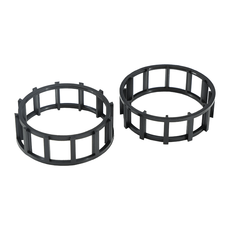

Black Plastic Cylindrical Roller Bearing Cage
-
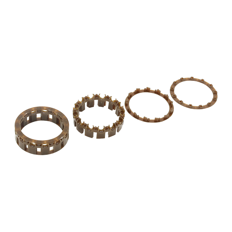
Nylon Cylindrical Roller Bearing Cage Assembly Unit
-
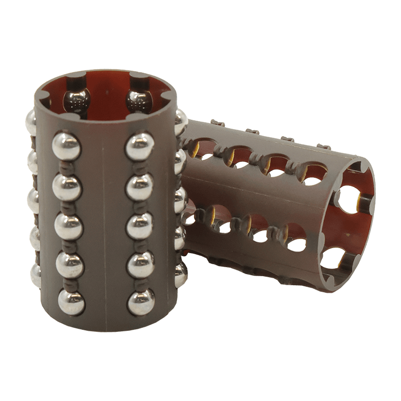
ZB Series Cylindrical Roller Bearing Cage
Cylindrical Roller Cages as the unsung heroes of bearing performance, these precision components serve as the vital backbone that maintains perfect roller alignment and spacing.
By effectively eliminating destructive metal-to-metal contact, our cages drastically reduce friction, heat buildup, and wear, ensuring your equipment operates at peak efficiency even under extreme loads or high speeds.
Engineered for versatility, our collection features robust designs tailored for diverse industries—from heavy-duty industrial gearboxes and wind turbines to high-performance automotive transmissions.
We utilize advanced materials and rigorous manufacturing standards to deliver superior stability, optimal load distribution, and extended service life.
Whether you need lightweight polymer cages for speed or reinforced steel for durability, our solutions are built to withstand the toughest challenges.
Don't let bearing failure halt your production; invest in reliability.
Choose our Cylindrical Roller Bearing Cages to empower your machinery with smoother rotation, reduced maintenance costs, and uninterrupted operation.
About Us
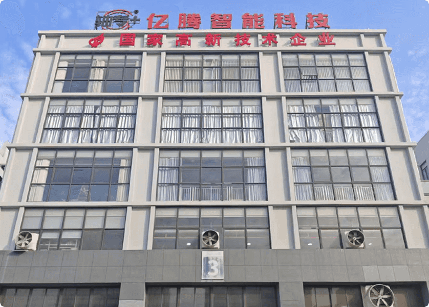
Jiaxing Yiteng Intelligent Technology Co., Ltd.
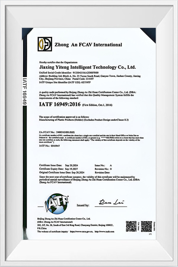
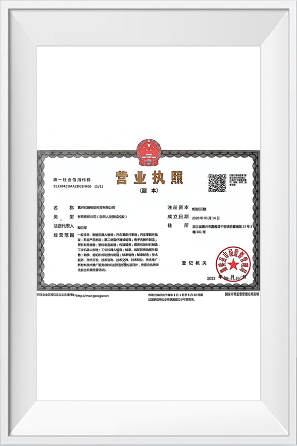
Jiaxing Yiteng Intelligent Technology Co., Ltd. is a manufacturer specializing in the production and processing of nylon cages, bearing cages, and other related products. Cylindrical Roller Cages Manufacturers and Cylindrical Roller Bearing Cages Factory. The company has a manufacturing tradition of over ten years since 2009, providing not only high-quality nylon cages and bearing components. We offer partnerships. Whether you are a global bearing OEM or a specialized distributor, our team adapts to your workflow. We combine our deep expertise in engineering plastics with a responsive, solutions-oriented mindset to reduce your procurement risk and enhance product performance. Our company maintains a complete and scientific quality management system. Jiaxing Yiteng Intelligent Technology Co., Ltd. has earned recognition within the industry for its integrity, strong capabilities, and product quality. Custom Cylindrical Roller Bearing Cages. We welcome friends from all walks of life to visit, provide guidance, and discuss business cooperation!
Message Feedback
Certificate Of Honour
News Center
-

 Industry News
 2026.10.15
If you have ever taken apart a small electric motor, a gear shift mechanism, or a conveyor idler, you have probably seen bearing staking without recognising it. A few small dents around a bore, a flattened rivet head, a deformed plastic boss — these are the visible traces of a joining process that ...VIEW MORE
2026.10.15
If you have ever taken apart a small electric motor, a gear shift mechanism, or a conveyor idler, you have probably seen bearing staking without recognising it. A few small dents around a bore, a flattened rivet head, a deformed plastic boss — these are the visible traces of a joining process that ...VIEW MORE
-
Industry News
2026.10.10
Running torque is one of those numbers that looks simple on a specification sheet and turns complicated the moment you try to use it. Ask three engineers what it means and you will get three slightly different answers: the drag you feel when you spin a bearing by hand, the steady torque a motor has...VIEW MORE
-
Industry News
2026.09.30
Ask a maintenance engineer what keeps a self-aligning bearing out of trouble, and the answer is usually raceways and lubrication. Ask a cage maker, and the answer sounds a little different. The spherical cage is the part that holds every roller or ball in its own pocket, at a controlled distance, w...VIEW MORE
Industry knowledge
Industry Knowledge
Guide Ring Design for High-Speed Cylindrical Roller Retention
Cylindrical roller cages face a unique retention challenge because the rollers have a large contact surface area against the pocket walls, and centrifugal force at higher rotational speeds pushes rollers outward against the outer pocket land with considerably more force than in ball bearing designs. Guide ring geometry, the raised rim structure that keeps rollers axially aligned within the cage, needs to be dimensioned with enough radial clearance to accommodate this outward force without generating excessive contact pressure that accelerates localized wear. Manufacturers typically validate guide ring clearance through actual high-speed spin testing rather than relying solely on static clearance calculations, since dynamic centrifugal loading behaves differently from the assumptions used in basic design formulas.
Pocket Land Width and Roller Skew Control
The land area between adjacent roller pockets in a cylindrical cage carries most of the structural load transferred between rollers during operation. Insufficient land width increases the risk of pocket wall deformation over time, particularly under shock loading conditions common in gearbox and industrial reducer applications. At the same time, excessively wide land areas reduce the number of rollers that fit within a given bearing envelope, lowering overall load capacity. Finding the optimal land width typically involves finite element stress analysis on the specific pocket geometry rather than applying a fixed ratio across different bearing sizes, since roller length-to-diameter ratio significantly affects how load concentrates at the pocket edges.
Comparing Snap-Type and Riveted Two-Piece Cage Construction
Cylindrical roller cages are produced in both one-piece snap-together designs and two-piece assemblies joined by rivets or ultrasonic welding, and the choice between these approaches affects both manufacturing cost and long-term structural reliability under different operating conditions.
| Construction Type | Assembly Cost | Structural Consideration |
| One-piece snap | Lower, single-shot molding | Limited to smaller roller diameters due to snap flexure limits |
| Two-piece riveted | Higher, added assembly step | Rivet joint becomes a potential fatigue point under vibration |
| Two-piece ultrasonic weld | Moderate, requires weld fixture validation | Weld joint strength depends heavily on process parameter control |
For larger roller diameters where a one-piece snap design would require excessive pocket wall flexure during roller insertion, two-piece construction becomes necessary regardless of the added assembly cost. Buyers should confirm which joining method a supplier uses for their specific bearing size range and request fatigue test data on the joint itself, since this is often the weakest structural point in a two-piece cage rather than the pocket walls.
Thermal Expansion Mismatch Between Cage and Housing Materials
Plastic cages have a significantly higher coefficient of thermal expansion than the steel rollers and raceways they operate alongside, which becomes an important design consideration in applications with wide operating temperature ranges, such as outdoor industrial equipment or systems near heat-generating machinery.
- Pocket clearance calculated at room temperature can tighten unexpectedly at elevated operating temperatures, increasing friction and heat buildup in a compounding cycle
- Guide ring diameter fit against the bearing race also shifts with temperature, and clearance calculated only at ambient conditions may not hold across the full service temperature range
- Glass fiber reinforcement reduces thermal expansion coefficient compared to unfilled resin, making filled formulations generally preferable for wide-temperature-range applications
- Cage designs intended for both cold-start and high-temperature continuous operation should be dimensionally verified at both temperature extremes, not just at nominal operating temperature
Requesting dimensional data at both the minimum and maximum specified operating temperatures, rather than only at room temperature, gives a clearer picture of whether a given cage design will maintain proper clearance across the full range an application will actually experience.
Factory Process Controls That Affect Batch-to-Batch Consistency
For OEM buyers placing recurring orders across multiple production runs, the consistency of a cage supplier's molding process matters as much as the initial sample quality, since drift in process parameters over time can introduce dimensional variation that passes individual batch inspection but causes cumulative fit problems across a larger installed base.
- Resin drying time and temperature control prior to molding, since inconsistent moisture content in hygroscopic nylons directly affects shot-to-shot dimensional stability
- Mold temperature control system calibration, checked on a scheduled interval rather than only at initial tooling qualification
- Cavity-to-cavity consistency tracking in multi-cavity tools, since individual cavities can drift out of tolerance independently of one another over extended production runs
- Statistical process control charting on key dimensions across production lots, rather than relying solely on first-article and final inspection checkpoints
Factories that share SPC trend data across production lots, rather than only pass/fail inspection summaries, give buyers much better visibility into whether a supplier's process is genuinely stable or simply passing inspection through wider acceptance tolerances. This distinction becomes particularly important for buyers integrating cages into automated assembly lines with limited tolerance for part-to-part variation.
Product Categories
Automotive Bearing Cages Needle Roller Bearing Cages Textile Machinery Ball Cages Industrial Ball & Linear Cages Cylindrical Roller Cages Engineering Plastic Parts & Accessories Cylindrical Roller Bearing CagesContact us

Phone:
+86 138 6736 9593
E-mail:
[email protected]
Address:
Building 3, No. 23 Yucao South Road, Ganyao Town, Jiashan County, Jiaxing City, Zhejiang ProvincePartner with Us for a Smarter Manufacturing Future!

Copyright © Jiaxing Yiteng Intelligent Technology Co., Ltd. All Rights
Reserved
Custom Cylindrical Roller Bearing Cages
