

 English
 中文简体
 عربى

YITENG
YITENG
YITENG
YITENG
YITENG
YITENG
YITENG
YITENG
YITENG
Content
A maintenance engineer in a textile plant recently traced a sudden bearing failure to a change nobody had checked. A new drive pulley increased belt tension, raising the radial load on the adjacent bearing from 6 kN to 8 kN. That one-third increase in load cut the calculated bearing life by roughly 60 percent. The bearing material was not at fault; the load assumption was.
The rule that follows from this example is simple: load controls everything else in bearing selection. Before comparing suppliers, before choosing a cage material, and before setting a lubrication interval, you need to know the actual loads acting on the bearing. This article explains how to calculate bearing loads in practice, which formulas to use, and where engineers most often make mistakes.
Start with Load Types Before Reaching for a Formula
Every load on a bearing can be resolved into a radial component, acting perpendicular to the shaft axis, and an axial component, acting along the shaft axis. This distinction is not academic. A bearing's load rating is specified by direction, and using the wrong component in the calculation is one of the most frequent causes of early failure.
Radial Load
Radial loads come from belt tension, gear tooth forces, shaft dead weight, and rotating imbalance. Deep groove ball bearings handle moderate radial loads with some axial capacity. Cylindrical roller bearings are stronger in pure radial applications because their line contact distributes the load over a larger area, but they generally need a separate axial location.
Axial Load
Axial loads appear in vertical shafts, helical gear trains, and thrust-dominated positions. A standard radial bearing has limited axial capacity in either direction. When the axial component dominates, engineers turn to dedicated thrust arrangements or to compact assemblies such as a thrust needle roller and cage assembly, which fits into tight axial spaces without a complex housing.
 AXK Series Thrust Needle Roller and Cage AssemblyThis compact flat thrust bearing handles heavy axial loads where space is tight, making it ideal for vertical shafts or helical gear trains that demand high axial capacity in a slim profile.View Product →
Combined and Moment Loads
Most real applications combine radial and axial components. An offset force also creates a moment load that tips the bearing cross-section and changes the load distribution inside the raceways, so it cannot be ignored when a gear or pulley sits far from the bearing support. The table below summarizes the three components.
| Load Component | Direction | Typical Source | Preferred Bearing Type |
|---|---|---|---|
| Radial | Perpendicular to shaft | Belt tension, gear mesh, rotor weight | Deep groove ball, cylindrical roller |
| Axial (thrust) | Parallel to shaft | Helical gears, vertical rotors, thrust loads | Angular contact ball, thrust needle roller assembly |
| Moment | Tipping about the bearing center | Cantilevered loads, misalignment, offset pulleys | Self-aligning ball, paired angular contact |
Static and Dynamic Loads: Two Ratings, Two Jobs
Static and dynamic do not mean "stopped" and "moving" in the everyday sense; they describe two different load ratings, each with its own purpose.
A static load applies when the bearing is stationary or oscillates very slowly and is not intended to rotate under the full load. The static load rating C0, defined in ISO 76, is the maximum load the bearing can accept without permanent deformation of the rolling elements or raceways. The check is the static safety factor:
s0 = C0 / P0
where P0 is the equivalent static load. For smooth, steady machinery, a static safety factor of 1.5 to 2.5 is common; for applications with shock loads, 3.0 or higher is recommended.
A dynamic load applies when the bearing rotates under load. The basic dynamic load rating C, defined in ISO 281, is the constant load that a bearing can carry for one million revolutions with 90 percent reliability. Fatigue spalling, rather than deformation, defines this limit. The table below compares the two ratings.
| Parameter | Static Load Rating | Dynamic Load Rating |
|---|---|---|
| Symbol | C0 | C |
| Condition | Bearing stationary or slow oscillation | Bearing rotating under operating speed |
| Failure Mode | Permanent indentation of raceways | Contact fatigue spalling |
| Design Check | s0 = C0 / P0 | L10 = (C / P)p |
The Core Formulas: Equivalent Load and Rating Life
The equivalent dynamic load P converts combined radial and axial forces into one value that can be compared with the dynamic load rating C. The general form is:
P = X × Fr + Y × Fa
where Fr is the radial load, Fa is the axial load, and X and Y are factors taken from the bearing catalog based on the internal geometry and the ratio Fa / Fr. For a bearing under a purely radial load, P equals Fr. Once P is known, the basic rating life is:
L10 = (C / P)p million revolutions
where p = 3 for ball bearings and p = 10/3 for roller bearings. To convert revolutions into operating hours:
L10h = (106 / (60 × n)) × (C / P)p
where n is the operating speed in revolutions per minute.
To see how quickly the result changes with input error, take a cylindrical roller bearing with a dynamic load rating C = 69.3 kN under a pure radial load of 12 kN at 1,450 rpm. The equivalent load P is 12 kN, and the life is:
L10 = (69.3 / 12)10/3 ≈ 346 million revolutions
L10h = (106 / (60 × 1,450)) × 346 ≈ 4,000 hours
Now double the load to 24 kN. Life falls by a factor of about 10, leaving roughly 400 hours. A 33 percent load miscalculation, as in the opening example, reduces life by roughly 60 percent. Accurate load input is therefore the most valuable refinement in the selection process.
The load level also decides how much responsibility the cage carries. In a heavily loaded cylindrical roller bearing, the cage must keep rollers evenly spaced under fluctuating forces and high acceleration. A machined or molded cage with precise pockets does this dependably.
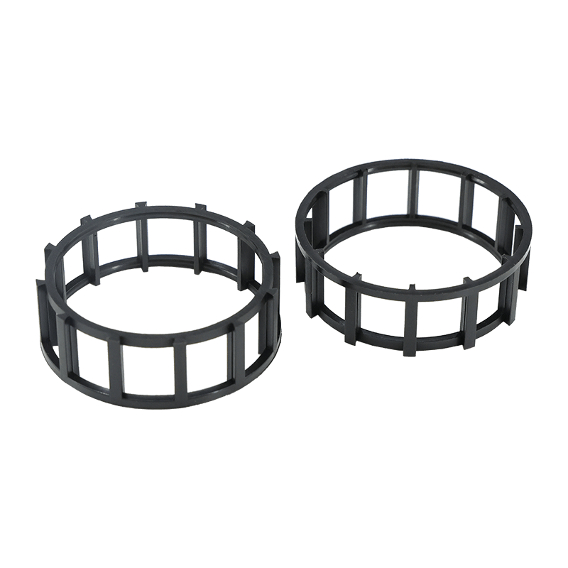 Plastic Cage for NJ Series Cylindrical Roller BearingsThis precision cage maintains roller alignment and prevents skewing in heavily loaded NJ-type bearings, ensuring even load distribution and reliable performance in motors, gearboxes, and compressors.View Product →
A Practical Sequence for Calculating Bearing Loads
Use the following sequence when you calculate bearing loads for a new machine or for an existing application that is being revised.
- Define the operating profile. List speeds, applied torque, temperatures, and the percentage of running time at each condition.
- Draw a force diagram. Include gear tooth forces, pulley tensions, shaft weight, and any external thrust or moment load.
- Resolve forces at each bearing position. Split every force into radial and axial components at the shaft location of each bearing.
- Calculate the equivalent dynamic load P. Use the X and Y factors from the bearing catalog for the selected bearing geometry.
- Apply application factors. Shock, vibration, and high temperature all reduce the allowable load. ISO 281 life modification factors cover these conditions.
- Select a preliminary bearing and check C / P. A ratio below 2 predicts a very short service life, while ratios of 3 to 5 are common for continuous industrial duty.
- Iterate. If the calculated life is too short, choose a larger bearing or reduce the load before finalizing the cage material and lubrication plan.
Load Calculation Errors That Shorten Bearing Life
Even experienced designers repeat certain mistakes. These five account for most cases where calculated life never matches field performance.
- Ignoring moment loads. A bearing at the end of a long cantilever experiences an overturning moment that distributes the load unevenly across its rows. Entering only the vertical force into the calculation understates the real peak contact stress.
- Using the static rating for dynamic duty. When the bearing rotates continuously, the governing value is the dynamic load rating C. Selecting from C0 alone leads to oversized assemblies and unnecessary cost.
- Averaging highly variable loads. The life equation is non-linear, and high-load intervals dominate the damage. Averaging 2 kN and 8 kN gives 5 kN, but the damage-equivalent load is about 6.4 kN for a roller bearing, and the real life is noticeably shorter.
- Overlooking temperature derating. Above roughly 120 °C, bearing steel loses hardness and the permissible load drops. Temperature factors should be applied before the life calculation, not after.
- Treating the cage as an afterthought. A correct load calculation can still end in failure if the cage cannot tolerate starting torque, shock, or overspeed. The cage distributes the rolling elements and indirectly controls load sharing; it needs the same attention as the raceways.
From Load Numbers to Cage Selection
Once the load calculation is complete, the next step is translating the result into a reliable bearing package. The cage keeps rolling elements evenly spaced and does not carry the main load itself, but it must survive the accelerations, speeds, and lubrication conditions that the load calculation defines.
Polyamide (nylon) cages dominate mass-production bearings because they are light, quiet, and can be molded with internal geometry that improves lubricant retention. They suit motors, automotive auxiliary drives, textile machinery, and many industrial applications. Matching the cage to the verified load profile is where a specialized bearing cage manufacturer adds value: pocket geometry, molding tolerances, and material selection all influence how evenly the load is shared across the rolling elements.
Automotive gearbox positions are a good example. Rapid load changes, oil splash lubrication, and high operating temperature demand a cage that resists both mechanical stress and chemical degradation. The cage must also survive repeated shock events that a steady-state load calculation may not fully capture.
 6V40 Automotive Gear Shift Bearing CageEngineered for the oscillating motion and thermal stress of transmission gear shifts, this cage preserves consistent roller spacing and shift feel over billions of cycles in demanding automotive environments.View Product →
When you evaluate supply options after completing the bearing load calculation, look beyond the cage price. Dimensional consistency, material traceability, and the supplier's experience with load-bearing cage designs matter more than the initial unit cost. A practical guide to selecting a plastic bearing cage factory outlines the quality checks worth performing during supplier qualification.
Calculating bearing loads correctly is not a formality; it is the foundation that every later decision stands on. If the load is right, the bearing size, cage type, and maintenance plan all fall into place. If the load is wrong, no material upgrade or premium lubricant will save the bearing from premature failure.